A stereo microscope is one of the most useful tools on an electronics repair or inspection bench.
Whether you are checking solder joints, replacing fine-pitch components, examining damaged PCB traces, repairing smartphones, inspecting connectors, or performing quality control, the microscope must do more than simply magnify the board.
A good electronics microscope needs to provide the right balance of:
Magnification
Optical resolution
Working distance
Field of view
Depth perception
Stand stability
Lighting
Ergonomics
Camera compatibility
This is why choosing a microscope based only on a specification such as “45× magnification” or “4K camera included” can lead to the wrong system.
For electronics work, more magnification is not always better.
In many cases, comfortable working distance, a wide field of view, stable mechanics, and smooth continuous zoom are more important than maximum magnification.
This guide explains how to choose a stereo microscope for electronics repair, PCB inspection, microsoldering, and industrial inspection.
Why Stereo Microscopes Are Ideal for Electronics Work
Electronic circuit boards are three-dimensional objects.
Components have height. Solder joints rise above the PCB surface. Connectors, wires, shielding, capacitors, IC packages, and mechanical structures all occupy different planes.
A stereo microscope is particularly well suited to this type of work because it provides two slightly different optical views to your eyes.
Your brain combines them into a stereoscopic image with useful depth perception.
That makes it easier to judge:
Component height
Tool position
Soldering iron position
Wire placement
Connector alignment
Surface contours
Solder joint shape
For manual work, this three-dimensional perception is a major advantage over a purely digital two-dimensional image.
What Can You Inspect with a Stereo Microscope?
A stereo microscope can be used throughout an electronics workflow.
Typical applications include:
PCB Inspection
Examine:
Solder joints
PCB traces
Pads
Vias
Through-hole joints
Connectors
Component alignment
Foreign material
Corrosion
Contamination
Microsoldering
Perform:
SMD component replacement
Connector repair
Jumper wire installation
Trace repair
Fine-pitch soldering
Rework
Hot-air inspection
Solder bridge removal
Smartphone and Consumer Electronics Repair
Inspect and repair:
Logic boards
Charging connectors
Small flex connectors
IC surroundings
Liquid damage
Damaged pads
Micro-components
Industrial Quality Control
Inspect:
Assembly quality
Solder defects
Component orientation
Mechanical damage
Surface contamination
Production defects
Failure Analysis
Look for:
Cracked solder joints
Burned components
Broken traces
Corrosion
Mechanical damage
Contamination
Poor assembly
The Most Important Specifications
When choosing an electronics stereo microscope, concentrate on these factors:
Magnification range
Zoom ratio
Optical resolution
Field of view
Working distance
Depth of field
Binocular or trinocular head
Illumination
Camera compatibility
Ergonomics
Let's examine each one.
1. How Much Magnification Do You Need?
Electronics work generally requires much less magnification than many first-time buyers expect.
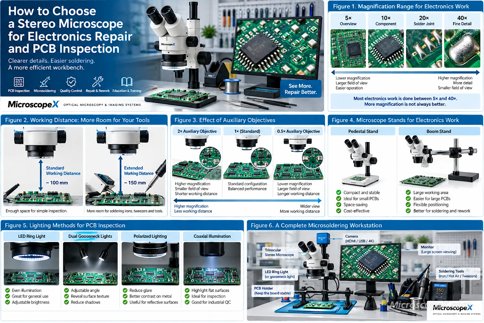
A typical zoom stereo microscope may provide a standard magnification range around:
7× to 45×
or:
6.5× to 65×
depending on the optical system.
With optional eyepieces and auxiliary objectives, some systems can extend significantly beyond this range.
But maximum magnification should not be your main goal.
For many PCB tasks, the most useful operating range is much lower than the microscope's maximum capability.
Typical Magnification for Electronics Work
The following ranges provide a useful general guide.
| Task | Typical Useful Magnification |
|---|---|
| General PCB inspection | 5×–15× |
| Component identification | 7×–20× |
| Solder joint inspection | 10×–30× |
| General microsoldering | 7×–25× |
| Fine-pitch components | 15×–40× |
| Trace and pad inspection | 15×–40× |
| Very small defects | 30×+ |
These are not strict rules.
The ideal magnification depends on:
Component size
Operator preference
Field of view
Working distance
Optical resolution
A technician rarely works continuously at maximum magnification.
Why Too Much Magnification Can Make Soldering Harder
Increasing magnification usually reduces:
Field of view
Depth of field
Working area visible at once
At very high magnification, even small hand movements become visually large.
This can make it harder to:
Navigate around the PCB
Bring tools into position
Follow a soldering iron
See surrounding components
Maintain orientation
For active soldering, a moderate magnification with a wide view is often more useful than maximum magnification.
Continuous Zoom Is Extremely Useful
For electronics work, a continuous zoom stereo microscope is usually preferable to a microscope with only two fixed magnification levels.
A zoom system lets you move smoothly from:
wide overview → component view → detailed inspection
without changing objectives.
For example:
Start at low magnification to locate the repair area.
Zoom in to inspect the component.
Perform the soldering operation.
Increase magnification again to inspect the finished joint.
This makes the workflow faster and more comfortable.
2. Zoom Ratio Explained
Do not confuse total magnification with zoom ratio.
A microscope with a zoom body such as:
0.7×–4.5×
has a zoom ratio of approximately:
6.4:1
With 10× eyepieces, that becomes approximately:
7×–45× total magnification
A larger zoom ratio provides more flexibility between low and high magnification without changing accessories.
For a multipurpose electronics workstation, this can be valuable.
3. Optical Resolution Matters More Than Maximum Magnification
Magnification makes an image larger.
Resolution determines whether additional detail is actually visible.
A microscope with excellent optics at 30× may reveal more useful information than a lower-quality system advertised at a much higher magnification.
Look for good:
Contrast
Sharpness
Flatness of field
Edge performance
Color correction
Fine PCB structures are high-contrast objects, so good optical quality can make solder boundaries, trace edges, contamination, and surface defects much easier to evaluate.
Avoid Empty Magnification
If increasing magnification simply makes the image larger without revealing additional detail, you have reached empty magnification.
This is one reason extremely high advertised magnification should not automatically be treated as a better specification.
For electronics, prioritize:
useful optical detail
rather than:
the largest magnification number
4. Field of View Is Critical
Field of view describes how much of the PCB you can see at one time.
A wide field of view makes electronics work much easier.
It allows you to:
Find components quickly
Follow PCB traces
See nearby components
Position tools
Move around the board
Maintain orientation
At low magnification, a good stereo microscope should give you a comfortable overview.
As you zoom in, the visible area becomes smaller.
Eyepiece Field Number Matters
Stereo microscope eyepieces may be marked with specifications such as:
WF10×/22
or:
WF10×/23
The second number relates to the eyepiece field number.
A larger usable field number generally allows a wider viewing field when matched to the microscope optical system.
For electronics work, wide-field eyepieces are desirable because they make the microscope feel less restrictive.
5. Working Distance May Be the Most Important Specification
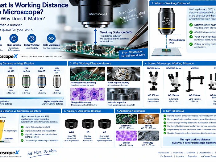
Working distance is the space between the front of the microscope objective and the specimen when the image is in focus.
For electronics repair, you need room for:
Soldering irons
Hot-air nozzles
Tweezers
Probes
Flux applicators
Wire
Component holders
Brushes
If the working distance is too short, your tools constantly collide with the microscope.
That can make an otherwise excellent optical system frustrating to use.
How Much Working Distance Do You Need?
There is no universal number, but electronics work generally benefits from a generous working distance.
Many stereo microscope systems provide working distances around or above 100 mm in standard or low-magnification configurations.
For active soldering, more working space is often better.
But working distance must be balanced against:
Magnification
Field of view
Optical resolution
Auxiliary objective choice
Auxiliary Objectives and Working Distance
Stereo microscopes can often accept auxiliary objectives such as:
0.5×
0.7×
1.5×
2×
These lenses change much more than total magnification.
For example, a 0.5× auxiliary objective typically:
Reduces magnification
Increases field of view
Increases working distance
This combination can be extremely useful for electronics repair.
It gives you:
more room + wider view + lower magnification
which is often exactly what a soldering workstation needs.
Example
Suppose a microscope provides approximately:
7×–45×
with its standard configuration.
Adding a 0.5× auxiliary objective may produce approximately:
3.5×–22.5×
while also increasing the working distance.
For large PCB work and microsoldering, that lower range can actually be more practical than the original higher magnification.
What About 2× Auxiliary Objectives?
A 2× auxiliary objective does the opposite.
It increases magnification but generally reduces working distance and field of view.
This can be useful for highly detailed inspection.
It is less ideal when you need a large amount of space for tools.
For electronics, many users benefit more from a low-power auxiliary objective than a high-power one.
6. Depth of Field Matters During Hand Work
Electronic assemblies are not perfectly flat.
A PCB may contain:
Tall capacitors
IC packages
Connectors
Wires
Solder joints
Shielding
Mechanical supports
A stereo microscope provides relatively good depth of field at moderate magnifications.
This allows objects at slightly different heights to remain reasonably clear.
As magnification increases, depth of field becomes shallower.
Another reason not to use more magnification than necessary.
7. Binocular vs Trinocular Stereo Microscope
This is one of the most important purchasing decisions.
Binocular Stereo Microscope
A binocular microscope has two eyepieces for direct observation.
It is sufficient if you only need to work through the eyepieces.
Advantages include:
Simpler design
Lower cost
Excellent direct stereo viewing
Suitable for manual soldering and inspection
Trinocular Stereo Microscope
A trinocular microscope adds a third optical port for a camera.
This allows you to keep the two eyepieces while connecting:
HDMI camera
USB camera
Measurement camera
Documentation system
For a professional electronics workstation, a trinocular configuration is often the more flexible long-term choice.
Why a Trinocular Microscope Is Useful
A camera can be used for:
Documentation
Before-and-after repair images
Training
Customer reports
Quality-control records
Video recording
Large-screen viewing
Measurement
Remote collaboration
You can still use the eyepieces for precise manual work while using the camera when needed.
Eyepieces or Monitor for Microsoldering?
Both approaches are possible.
Working Through the Eyepieces
Advantages:
True stereoscopic depth perception
Essentially immediate optical response
Excellent hand-eye coordination
Natural depth judgment
This remains a very strong option for precise manual soldering.
Working Through a Monitor
Advantages:
More ergonomic head position in some setups
Large image
Easy sharing
Convenient recording
Good for training
Useful for inspection
However, monitor-based soldering depends heavily on:
Camera latency
Frame rate
Display latency
If you intend to work entirely from a screen, choose the camera carefully.
8. Choosing the Right Microscope Stand
The microscope optics may be excellent, but a poor stand can make the complete system difficult to use.
For electronics, stand choice is especially important because PCB sizes vary considerably.
Common options include:
Articulating stand
Pedestal or Pole Stand
A traditional base stand is compact and stable.
It works well for:
Small circuit boards
Smartphone logic boards
Small components
Inspection stations with limited space
Advantages:
Compact
Stable
Easy to set up
Usually less expensive
The main limitation is the size of the base.
A large PCB may collide with the microscope stand or base plate.
Boom Stand
A boom stand is often one of the best options for electronics work.
Instead of positioning the microscope directly over a fixed base plate, the microscope head is mounted on an extended horizontal arm.
This provides a much larger usable workspace.
Advantages include:
Large PCB clearance
Flexible microscope positioning
Easy movement across a workbench
More room for soldering equipment
Better access to large boards
For motherboard repair, industrial PCBs, and general-purpose electronics work, this flexibility can be extremely valuable.
Single-Arm vs Double-Arm Boom Stands
Boom stands vary in mechanical design.
A simpler single-arm design can provide excellent flexibility for many users.
Heavier double-arm or more robust boom systems can provide additional stability for larger microscope heads, cameras, accessories, and demanding workstations.
The key requirement is:
The microscope should stay where you place it.
If touching the focus control causes the image to shake significantly, the stand is not rigid enough for precision work.
Stand Stability Matters at High Magnification
Small mechanical vibrations become much more visible as magnification increases.
A good electronics microscope stand should resist:
Desk vibration
Focus adjustment movement
Camera weight
Accidental bumps
Arm sagging
When comparing microscope systems, mechanical stability deserves almost as much attention as optical specifications.
9. Lighting: The Most Underrated Part of the System
Even an excellent microscope produces a poor image if the specimen is badly illuminated.
PCB surfaces are particularly challenging because they contain:
Shiny solder
Matte solder mask
Reflective metal
Black IC packages
White silkscreen
Copper
Flux residue
One lighting system may not be ideal for every feature.
LED Ring Light
An LED ring light surrounds the microscope objective.
It is one of the most common illumination systems for stereo microscopy.
Advantages:
Bright
Compact
Easy to install
Relatively even illumination
Good general-purpose PCB lighting
For routine electronics inspection, an adjustable LED ring light is an excellent starting point.
Why Brightness Control Matters
Maximum brightness is not always desirable.
Highly reflective solder can produce strong highlights.
Adjustable intensity allows you to reduce glare and improve surface contrast.
A good ring light should allow smooth brightness adjustment.
Dual Gooseneck Illumination
A dual gooseneck light uses movable light guides or LED heads that can illuminate the sample from different angles.
This can be extremely useful when you want to emphasize:
Surface texture
Scratches
Component edges
Solder shape
Raised defects
Directional light creates shadows that reveal surface relief more clearly than perfectly uniform illumination.
Ring Light vs Gooseneck Light
Ring Light
Best for:
General PCB inspection
Uniform illumination
Routine soldering
Fast work
Gooseneck Light
Best for:
Directional inspection
Surface defects
Texture
Contour inspection
Adjustable shadows
A professional workstation may use both.
Polarized Illumination
Reflective surfaces can create strong glare.
Polarization can help reduce certain specular reflections and reveal details that are otherwise difficult to see.
This can be helpful when inspecting:
Shiny solder
Metallic components
Reflective surfaces
Flux residues
Polarized lighting is not essential for every electronics workstation, but it can be a useful advanced option.
Coaxial Illumination
Coaxial illumination directs light approximately along the same optical axis used for observation.
It can be valuable for certain flat reflective structures.
Applications may include:
Semiconductor surfaces
Flat metallic structures
Highly reflective samples
Certain industrial inspections
For ordinary PCB soldering, a ring light is usually simpler.
For specialized inspection, coaxial illumination can reveal different types of detail.
10. Choosing a Camera for PCB Inspection
If you select a trinocular stereo microscope, the next question is the camera.
Camera priorities for electronics differ from those of scientific fluorescence imaging.
For PCB work, consider:
Resolution
Frame rate
Latency
Sensor size
Field of view
HDMI output
USB connectivity
HDMI Cameras for Electronics
HDMI cameras are particularly convenient for electronics because they can connect directly to a monitor.
The basic workflow is:
Microscope → Camera → HDMI Monitor
Advantages include:
Simple operation
No computer required
Large-screen viewing
Low-latency output with suitable hardware
Convenient inspection
Easy teaching and demonstration
A 4K HDMI camera can be very useful for detailed PCB inspection on a large 4K monitor.
Why FPS Matters for Microsoldering
If you perform soldering while looking at the monitor, frame rate becomes especially important.
For static inspection:
4K at 30 FPS
can provide excellent detail.
For active soldering:
1080p at 60 FPS
or higher can provide smoother tool movement.
A camera that supports both high-resolution and high-frame-rate modes can therefore be particularly useful.
USB Cameras
USB cameras are valuable when you need computer-based functions such as:
Measurement
Annotation
Image capture
Video recording
Reporting
Image analysis
Data storage
For quality-control and measurement applications, USB3.0 connectivity can be particularly useful.
HDMI + USB Cameras
A multi-interface camera can provide the advantages of both.
For example:
HDMI → live monitor
and:
USB → computer software
This is an attractive configuration for multipurpose electronics and inspection workstations.
11. Camera Sensor Size and Field of View
Camera sensor size influences how much of the microscope image is captured.
A larger sensor generally captures a wider portion of the available image circle when other optical factors remain unchanged.
A smaller sensor captures a narrower portion.
This matters in PCB inspection because a very narrow camera field can make navigation difficult.
C-Mount Adapter Selection
The C-mount adapter connects the microscope's imaging port to the camera.
Adapter magnifications may include values such as:
0.35×
0.5×
0.63×
1×
A reduced-magnification adapter can help a smaller camera sensor capture a wider field.
The correct combination depends on:
Microscope optical system
Camera sensor size
Desired field of view
Image circle
Do not treat the C-mount adapter as an unimportant accessory.
A poorly matched adapter can make an otherwise excellent camera system frustrating to use.
12. Ergonomics Matter More Than You Think
Electronics technicians may spend hours at the microscope.
Poor ergonomics can cause:
Neck discomfort
Shoulder fatigue
Eye strain
Back discomfort
Reduced concentration
A professional microscope should be configured around the operator.
Microscope Height
The eyepieces should be positioned so that you do not need to bend your neck excessively.
A stand with good vertical adjustment makes this easier.
Eyepiece Angle
Many stereo microscope heads use an inclined viewing angle.
This helps maintain a more natural posture.
Ergonomic heads and adjustable viewing angles can be especially useful for extended work sessions.
Eye Relief and Eyepieces
If you wear glasses, high-eyepoint eyepieces can be more comfortable.
Also look for:
Diopter adjustment
Adjustable interpupillary distance
Comfortable eyecups
Proper adjustment reduces eye strain and helps both eyes focus comfortably.
Keep the PCB at a Comfortable Height
Do not solve every positioning problem by adjusting only the microscope.
The workpiece itself can also be raised or supported.
PCB holders can help keep the board:
Stable
Level
Rotatable
Easy to reposition
A good bench setup treats microscope, board holder, lighting, and tools as a single workstation.
13. Do You Need a Digital Microscope Instead?
Digital microscopes can also be useful for electronics.
They offer:
Monitor-based viewing
Easy documentation
Compact design
Digital measurement
Convenient sharing
But a traditional optical stereo microscope still has an important advantage for delicate manual work:
true optical stereo depth perception
If soldering and manipulation are central to the workflow, a stereo optical microscope remains an excellent choice.
If inspection, measurement, and documentation are more important than hand manipulation, a digital microscope may also be attractive.
14. Greenough vs CMO Stereo Microscopes
Professional stereo microscopes commonly use one of two broad optical architectures.
Greenough Design
A Greenough stereo microscope uses two separate angled optical systems.
Advantages often include:
Compact design
Good stereoscopic effect
Cost efficiency
Excellent general-purpose performance
It is widely suitable for electronics work.
Common Main Objective — CMO
A CMO stereo microscope uses a shared main objective with separate optical paths farther into the microscope.
Advanced CMO systems can support:
Higher optical performance
Modular accessories
Specialized illumination
Cameras
Measurement systems
Advanced research configurations
For routine electronics repair, a good Greenough zoom stereo microscope can be entirely sufficient.
For demanding industrial inspection or modular imaging systems, a higher-end CMO system may offer additional flexibility.
Recommended Configurations by Use Case
Rather than searching for one universally “best” microscope, choose a configuration based on the work.
Configuration 1: General Electronics Repair
Recommended starting point:
Continuous zoom stereo microscope
Approximately 7×–45× standard range
Wide-field 10× eyepieces
Long working distance
LED ring light
Stable pedestal or boom stand
Binocular or trinocular head
Best for:
General PCB repair
Connectors
SMD components
Hobby electronics
Maintenance
Configuration 2: Professional Microsoldering
Recommended configuration:
High-quality continuous zoom stereo microscope
Wide field of view
0.5× auxiliary objective where appropriate
Long working distance
Trinocular head
Heavy boom stand
Adjustable LED ring light
Optional directional lighting
HDMI camera
High-frame-rate mode
Large monitor
Best for:
Smartphone logic boards
Fine PCB repair
Connector repair
Trace reconstruction
Component replacement
Daily professional soldering
The 0.5× auxiliary objective can be particularly useful because it creates more space for tools.
Configuration 3: PCB Quality Control
Recommended configuration:
Trinocular zoom stereo microscope
High optical resolution
Stable stand
Camera system
HDMI and/or USB output
Measurement software where required
Adjustable illumination
Camera calibration capability
Best for:
Production inspection
QC documentation
Assembly verification
Defect reporting
Measurement
Configuration 4: Large PCB and Motherboard Repair
Recommended configuration:
Zoom stereo microscope
Long working distance
Boom stand
Wide-field eyepieces
Low-power auxiliary objective
Large work surface
Ring light
Optional camera
The boom stand becomes especially important because large boards need to move freely beneath the microscope.
Configuration 5: Semiconductor and Fine-Detail Inspection
Recommended configuration:
Higher-resolution stereo optical system
Extended magnification capability
High-quality objectives
Stable precision stand
Specialized illumination as required
High-resolution camera
Measurement capability
At this level, optical quality becomes more important than simply achieving a high magnification number.
What Should You Spend More Money On?
If the budget is limited, prioritize components in roughly this order:
1. Optical Quality
The microscope optics determine what you can actually see.
2. Stable Stand
A great optical head on an unstable stand is difficult to use.
3. Working Distance
Especially important for soldering.
4. Good Lighting
Lighting can transform image quality.
5. Ergonomics
Important for daily professional use.
6. Camera
Add or upgrade the camera based on documentation and screen-viewing needs.
This is generally a better strategy than buying a poor optical microscope simply because it includes an impressive camera specification.
Common Buying Mistakes
Mistake 1: Buying the Highest Magnification Available
Higher magnification is not automatically more useful.
For electronics, field of view and working distance matter enormously.
Mistake 2: Ignoring Working Distance
A microscope may produce a beautiful image but still be difficult to solder under if there is not enough space for tools.
Mistake 3: Buying a Stand That Is Too Small
Small stands can restrict large PCBs.
For large-board repair, consider a boom stand.
Mistake 4: Ignoring Stand Stability
Vibration becomes highly visible at higher magnification.
A rigid stand is essential.
Mistake 5: Choosing a Camera Before the Microscope
Start with the optical microscope.
Then select a camera and adapter matched to it.
Mistake 6: Assuming 4K Automatically Makes a Better Microscope
Camera resolution cannot compensate for poor optics.
4K is valuable when the optical system provides useful detail for the camera to capture.
Mistake 7: Ignoring FPS and Latency
For screen-based microsoldering, smooth and responsive video can matter more than maximum resolution.
Mistake 8: Using Only Maximum-Brightness Ring Lighting
Bright reflections from solder can hide details.
Adjust illumination intensity and direction.
Mistake 9: Ignoring Ergonomics
A microscope that feels acceptable for five minutes may become uncomfortable after several hours.
Quick Buying Checklist
Before purchasing a stereo microscope for electronics, ask:
Magnification
Does the microscope provide a useful continuous zoom range?
Optical Quality
Is the image sharp and high contrast across the field?
Working Distance
Is there enough room for soldering tools and tweezers?
Field of View
Can you see enough of the PCB to work comfortably?
Stand
Will your board fit beneath it?
Stability
Does the microscope remain steady while focusing?
Head Type
Do you need a camera now or later?
If yes, consider trinocular.
Lighting
Is the brightness adjustable?
Would directional or polarized lighting help?
Camera
Do you prioritize:
Inspection detail?
Live soldering?
Documentation?
Measurement?
Ergonomics
Can you work comfortably for extended periods?
Frequently Asked Questions
What magnification is best for PCB soldering?
There is no single ideal magnification.
For general microsoldering, moderate magnification is usually easier to work with than extreme magnification.
Many tasks fall somewhere around 7×–25×, with higher magnification used for detailed inspection.
The ideal setting depends on component size and operator preference.
Is 45× enough for electronics repair?
For most general PCB inspection and microsoldering tasks, a stereo microscope reaching approximately 40×–45× provides substantial magnification.
Higher magnification can still be useful for specialized inspection, but it is not automatically necessary for routine repair.
Is a 0.5× objective good for soldering?
It can be extremely useful.
A 0.5× auxiliary objective generally lowers magnification while increasing field of view and working distance.
That creates more room for tools and often makes soldering more comfortable.
Should I buy a binocular or trinocular microscope?
Choose binocular if you only need direct optical observation.
Choose trinocular if you want to add a camera for:
Recording
Documentation
Monitor viewing
Training
Measurement
For professional use, trinocular provides more future flexibility.
Is a boom stand necessary?
Not always.
For small PCBs, a pedestal or pole stand may work very well.
For large motherboards or boards that need frequent repositioning, a boom stand can provide much more working freedom.
Is a digital microscope better for soldering?
Digital microscopes are convenient, but an optical stereo microscope provides true stereoscopic depth perception.
For highly precise hand work, many users benefit from direct stereo viewing.
A trinocular stereo microscope can provide both optical viewing and digital imaging.
Is 4K necessary for microsoldering?
No.
4K can be excellent for detailed PCB inspection.
For active soldering, smooth frame rate and low latency may be just as important.
A camera capable of 4K inspection and high-frame-rate 1080p operation can be a very versatile solution.
What lighting is best for PCB inspection?
An adjustable LED ring light is an excellent general-purpose solution.
Directional gooseneck lighting can help reveal surface relief, while polarized or specialized illumination can help with reflective surfaces.
The best lighting depends on what defect or structure you are trying to see.
Can I use a stereo microscope for very small SMD components?
Yes.
A good zoom stereo microscope is widely suitable for small SMD inspection and rework.
For extremely fine structures, choose optics with sufficient resolution and increase magnification only as much as necessary.
Conclusion
The best stereo microscope for electronics repair is not necessarily the microscope with the highest magnification or the most impressive camera.
A good electronics microscope should give you:
Sharp optics
Continuous zoom
A wide field of view
Useful depth perception
Long working distance
A stable stand
Adjustable illumination
Comfortable ergonomics
For general electronics work, a continuous zoom stereo microscope with a generous working distance and adjustable LED illumination provides an excellent foundation.
For professional microsoldering, adding:
A low-power auxiliary objective
Trinocular head
Stable boom stand
HDMI camera
High-frame-rate video
can create a highly flexible workstation.
For industrial inspection and quality control, camera integration, measurement, specialized illumination, and higher optical performance may become increasingly important.
The key is to select the microscope as a complete working system:
Optics + magnification + working distance + stand + illumination + camera + ergonomics
When all of these elements are properly matched, a stereo microscope becomes much more than a magnifying device.
It becomes one of the most important precision tools on the electronics workbench.
Explore Stereo Microscopes for Electronics and Industrial Inspection
MicroscopeX provides stereo microscopy systems for electronics repair, industrial inspection, measurement, education, research, and precision observation.
Available configurations include:
Continuous zoom stereo microscopes
Binocular systems
Trinocular systems
Pedestal stands
Boom stands
Industrial inspection configurations
Digital imaging systems
Measurement systems
Long-working-distance configurations
For digital documentation and monitor-based inspection:
Need help selecting magnification, stand, working distance, illumination, or camera configuration?
Contact MicroscopeX for complete electronics inspection and microscopy system support.